short description
![]() Automated Valve-Guide Inspection
Machine Type VF2
Automated Valve-Guide Inspection
Machine Type VF2
short description
 Setup
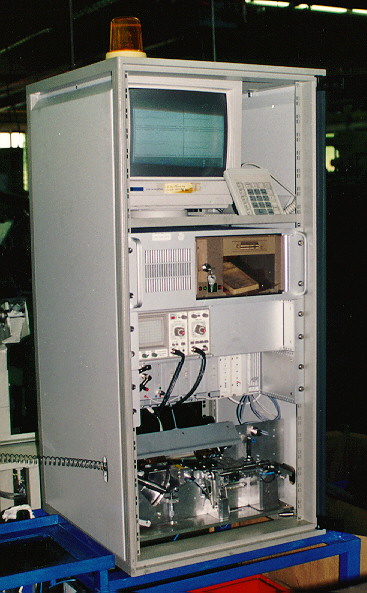
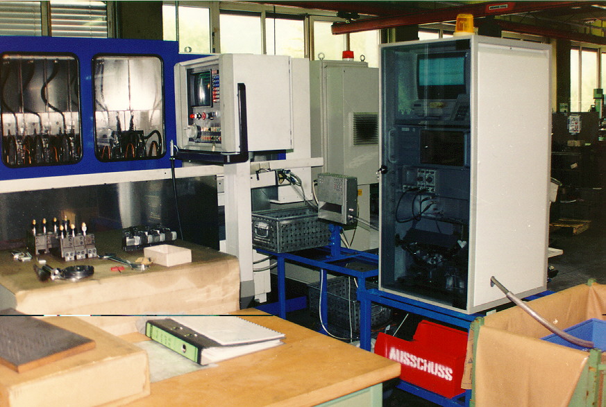
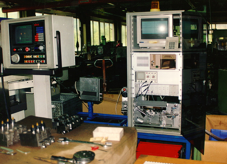
SetupThe valve-guide (VG) inspection machine is installed in a 19" rack. The bottom rack contains the optical measurement and handling unit. Above it are all electronic boards for measurement, controls and interface, an oscilloscope and the power supply. The 14" color monitor, the computer and a numerical keypad can be found in the top. The VG inspection machine is shielded from environmental influences by front and rear glass doors.
 Operational Principle
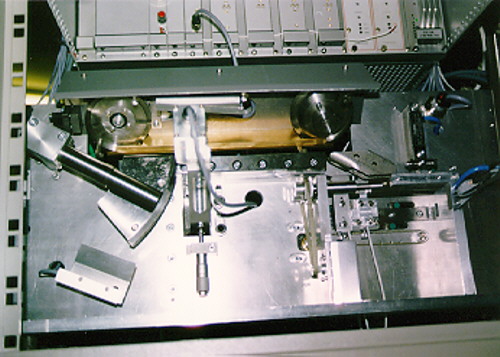
The sintered VG, having been finished in an automatic grinding machine and automatic lathe, comes oriented into a guiding prism. Each VG is then moved by slide pins through two visible laser beams. The shadow image projected on the CCD-chip has a pixel dimension equivalent to 5µm. The computer processes the image and calculates all dimensions, chamfers and radii. The measured or the processed image with calculated dimensions can be shown in real time for each VG on the monitor.
After the optical measurement the VG is transported to the crack and excentricity measuring station. Two contactless sensors scan the head of a rotating VG. Analysing their signals the computer evaluates the excentricity and the cracks on the turned part of the VG.
The computer compares all dimensions and crack-parameters with the programmed tolerances. A VG within the tolerance gaps passes the outlet to the package container. The rejected VGs drop into two boxes, one for wrong dimensions, the other for cracks.
 Mechanics
The mechanics are wear-resistant, maintenance-free and require little adjustments. The rotating parts are driven by step motors, the reject switches are driven by pneumatic cylincers.
The power part consists of four driver modules for the step motors. For the sensors, laser and camera different boards are provided. A built-in oscilloscope permits easy adjustment of the laser and the crack detector. The computer is built in a sliding rack. The data are stored in lithium battery buffered solid state memory.
 Operation
After turning power on, an automatic test is started. On the monitor a logon message appears, reporting the current status and then a list of actions. The program is menu-guided with automatic prompting of the required steps. This operational mode is the normal state of the machine. If the operator chooses, he can display the scanned image with calculated dimensions, the crack signal, the statistics etc. Further modes for programming, calibrating and tests are provided. The keypad allows to control the machine while keeping measured parts in view. Important quality control parameters can be changed only by using an authorization code. In case of parameter changes, the date/time and the identification number of the person who is making the change is stored. When a "stop" is issued, a signal for stopping the machine which feeds the VG inspection unit is generated. If the stop is caused by an error function, a lamp on the top of the rack blinks. The monitor displays the reason for the stop.
| VG size: | Ø 9 - 15 mm, Lmax 45 mm |
| Cycle time: | up to 1s, independing on VG size |
| Resolution: | 5 µm |
| Accurcy: | "x"- direction: 5 µm "y"- direction: < 1 µm, depending on the surface |
| Power supply: | 220-230V, 50-60Hz, 150W |
| Air pressure: | 6 bar |
| Dimensions: | ca. 560 x 600 x 1200 mm³ |
| Weight: | approx. 100 kg |